|
|
|
 |
|
|
|
Building and Using Maui's Tanawa
by Bertram Cooper
(Full text of article from Fall 2001 21st Century)
|
The Equatorial Circle
The Annual Circle
Proof of Principle
What Is a Torquetum?
Equations of Time
|
|
 |
|
|
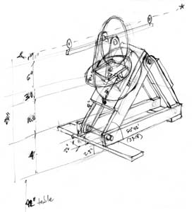
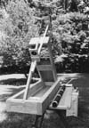
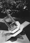
SKETCH OF A PROTOTYPE OF THE TORQUETUM
This sketch was the draft design for the torquetum shown in the photos, with a 14-inch hour circle.
|
These photos show the assembly of a primitive wooden torquetum (a model of Maui's tanawa), in preparation for celestial observations. Obviously, the torquetum was photographed during daylight hours, but a primary use of the instrument would be for stellar and planetary observations, and measurements of the Moon's motion.
The instrument's "lower unit"is raised up, from its horizontal frame to the angle of the co-latitude of the observer (90 degrees minus latitude), such that the polar axis of the hour circle will be parallel with the polar axis for the rotation of the Earth.
The direction of the polar axis can be established by first laying out a good south line at the planned point of observation, so as to provide a local "anchor"from which to measure time across the sky.
Polar north can be determined over the course of a 12-hour or longer night, to a high degree of precision, by locating the eastern and western elongation of any bright circumpolar star, and then splitting the difference. This can be supplemented with daytime observations of the Sun at noon, if you can find noon.
Given the present location of the vernal equinox, the north star is not true north, but is within three quarters of a degree of polar north. Sights can be made to accurately shoot astronomical north, and to establish a true north-south line for the setup.
Here (Photo 1), the sights are installed for a polar sighting and alignment, by a groove cut into the endplate of the lower unit. It must be noted that Maui was travelling approximately 2,200 years ago, and our present pole star was, at that time, farther from the position of the celestial pole. However, Maui would have found true astronomical north to be somewhere near the midpoint between Beta Ursa Minoris, and Polaris.
|
 |
 |
 |
 |
 |
| Photo 1 |
Photo 2 |
Photo 3 |
Photo 4 |
Photo 5 |
|
|
|
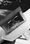
Another view of the setup (Photo 2), shows the frame of the instrument, parallel to the Earth's axis, and parallel to an instrument circle to be placed on the frame, which will give the right ascension along the celestial equator.
This setup is one in which the sights would be used at night for a polar alignment of the frame. Unlike the arrangement for daytime use, here the crosshairs are put as a front sight, and the rear sight is a 1/4" diameter hole, like the peep sight on a rifle.
The yoke with its wooden bearings now awaits assembly. It is awkward to set up the circles and bearings with the instrument in place, so this was done at a separate work table. The notched crosspiece in the yoke will ultimately support the sights. In the middle, a 23.5-degree wedge was made to imitate the inclination of the Earth's axis relative to the plane of the solar system. This circle must be set daily for the Sun's position on the ecliptic.
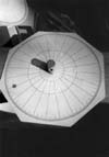
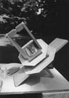
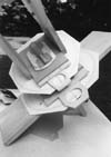
The Equatorial Circle
The 14-inch equatorial circle (Photo 3) takes a fair amount of time to construct, and easily competes with truing-up bearings in terms of patience and the extended concentration required for success. It is constructed with compass and dividers, first dividing the circle into sixths, producing six 60-degree lines; and then dividing each sixth by one-half, and then one-half again, producing twenty-four 15-degree (or one-hour) lines.
Using dividers, each hour is then divided into thirds, producing three 20 minute lines at 5-degrees each; each of these is then divided into fifths, to produce five 1-degree lines (4 minutes). Each degree is then divided into halves, producing one-half degree lines.
It is extremely important that the instrument move smoothly. We do not know what substance Maui used, but we used talcum powder to lubricate the movement of the circle with its adjoining surface, the bottom of the 23.5-degree wedge of obliquity. Dried clay from a river bed would work just as well.
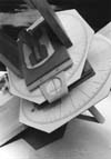
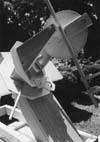
After the 14-inch equatorial circle has been installed on the instrument's polar axis, the 23.5-degree wedge is installed, with its main bearing (Photo 4). Talc is provided here too, so that the wedge, with yoke and sights installed, will turn smoothly on the fixed wooden bearing and hour circle. Any jerky movement of the sights against the hour circle will prohibit accurate readings of the stars later on.
The main bearing, which controls tension in the rotation of the sighting bar against the equatorial circle, is controlled by a compression of matted material such as horsehair; we used the underlining for a rug. A keeper bar is inserted to hold things in place temporarily. The bearing for the yoke and sighting bar is then installed into the upper plate of the 23.5-degree wedge, with its keeper bar.
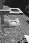
The Annual Circle
A 12-inch annual circle, marking degrees longitude from the vernal equinox, is then mounted, on the upper bearing, along with the sighting bar yoke (Photos 5 and 6). This is held in firm compression by paper wedges. There is no need for smooth motion on this bearing, as it is set only once for each day or evening, and does not change during an observation session.
|
|
|
|
 |
 |
 |
 |
| Photo 6 |
Photo 7 |
Photo 8 |
Photo 9 |
|
|
|
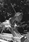
The vertical circle, marked off to 1/2 a degree, is then installed, which, when mounted on the annual circle, will give a direct reading (without calculation) of the celestial latitude of the planets and the Moon, above or below the ecliptic (Photo 7). When mounted directly on the hour circle, without the wedge of obliquity, this circle will give a direct reading of the declination of celestial objects, above or below the celestial equator.
Then the index mark for the declination circle—a piece of thread, held in place with glue—is installed; and the index mark for the 12"annual circle is installed (Photo 8).
This completes the assembly of the instrument, which is now ready for mounting into its lower unit, as shown in Photo 9. It may seem that we are ready to mount the sighting bar and its sights; but first, we have to provide tension for compression on the "horsehair"of the main bearing, for smooth motion of the hour circle.
A lower plate, with crossbar and compression wedges is provided, to put the 14-inch equatorial circle in mild compression, removing as much play as possible between it and the lower plate of the 23.5-degree wedge, while still at the same time providing smooth motion.
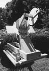
Then, the sighting bar with sights is mounted (Photo 10).
Various sighting systems were investigated. The best results so far, for daytime solar observations, were a front sight consisting of a 1/4-inch hole in a piece of hardboard. The middle "sight"is a crosshair, which is used for alignment of the Sun's image. This crosshair consists of two threads, which are glued in place. The rear "sight"is a sheet of paper, which catches the image of the Sun (through the aperture of the 1/4-inch front sight) with the crosshair superimposed (Photo 11).
|
|
|
|
 |
 |
 |
 |
| Photo 10 |
Photo 11 |
Photo 12 |
Photo 13 |
|
|
|
For nighttime observations, there are only two sights used: with the cross-hairs becoming the front sight, and the hardboard with the quarter inch hole becoming the rear sight. A surveyor's technique proved useful: When sighting, keep both eyes open and the mind focussed and concentrated only upon the celestial object—not upon the sight or the crosshair.
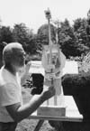
A sighting on the Sun is then collimated by two separate motions (Photo 12). For a right-handed person, the vertical motion of the sighting bar is controlled by the right hand, and is moved up and down only as required.
The horizontal motion of the instrument is controlled by the turning bar, held in the left hand, which is braced by the cross. Under no circumstances should torque be applied to the sighting bar. When crosshairs are visible and in focus, the image of the Sun can be captured easily to an accuracy of a quarter of a degree, or a minute of time, or less (Photo 11).
Photo 13 shows a view of the east side of the torquetum. The longitudinal position of the Sun along the ecliptic affects the adjustment of the entire instrument.
Proof of Principle
For our first "proof-of-principle"experimental observations of the motion of the Moon, in order to determine longitude on Earth, our measurements were done with a "stripped down"torquetum, without the 23.5-degree wedge installed. This minimal torquetum had only the 14"equatorial circle, pointing to the celestial equator, which directly measured a sidereal angle along the celestial sphere, known as lunar distance.
|
|
|
What Is a Torquetum?
The torquetum, an analogue computer, can tell us, without long and tedious calculation, at any time of the night when planets or the Moon are visible, what their angular distance is from the Sun, or from the first point of Aries, and/or from some bright star in their vicinity. It can also tell us how much they are above or below the ecliptic.
This would give us a fairly quick way to construct an almanac, with enough data to predict at least lunar eclipses, as well as occultations of bright stars or planets by the Moon—the which dramatic events ought to confirm the longitude readings obtained by using the torquetum to measure lunar distance.
—Rick Sanders
|
|
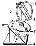
1. The circle that measures ecliptic latitude, that is, the number of degrees above or below the ecliptic of the Moon or the planets. It is properly calibrated when it reads "zero" every day at noon, when sighting the Sun.
2. A half-circle and plumb-bob attached to the sighting arm, which gives the elevation of a star or planet above the horizon.
3. Equatorial plane, points to the celestial equator, by tilting it from the horizontal by an angle equal to the co-latitude. The 14"circle on it is divided up into hours, for sidereal time or right ascension (when necessary, these readings can easily be converted into degrees, since 1 hour = 15 degrees).
4. Base, in the plane of the observer's horizon, oriented so that the axis of symmetry is on the north-south meridian.
5. Ecliptic plane, also known as the 23.5-degree wedge, set parallel to the plane of the ecliptic. The 12"circle on this plane is divided up into 24 hours, giving ecliptic longitude, where the position of the Sun is the sidereal time at noon for that day.
6. Sighting arm, with sights for "shooting"a planet, star, the Moon, or the Sun.
Source: Adapted from Sentiel Rommel, "Maui's Tanawa: A Torquetum of 232 B.C.," 21st Century, Spring 1999, p. 75.
|
|
|
|
|
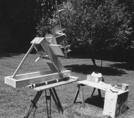
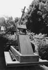
Photo 14
|
|
|
A view from the east (Photo 14) shows the completed torquetum, equipped with solar sights, in a setup ready for the recording of observations.
With our torquetum assembled, we can now start gathering a wealth of data, particularly the declination of the Sun at noon, and the equation of time (by contrasting our digital watches with the Sun's arrival on the south line every day). The notorious equation of time, caused by the apparent "speeding up"and "slowing down"of the Sun, will force us to reflect on the fact that the solar system does not allow itself to be forced into arbitrary circles with uniform motions.
For example, why do the equations of time make two peaks and two valleys during the course of the year (see table), while declination has only one peak and one valley during the year? Why are the equations of time not zero at the equinoxes? Why are the number of days between the seasons not equal?
|
|
|
|
|
|
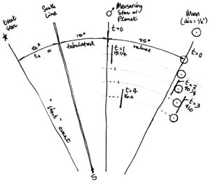
Note that a sequence of four shots, paced evenly at about one minute per shot, which is a natural and adequately unhurried pace, such as Maui might have used, minimizes the error. This sequence is (1) one on the reference star, (2) one on the trailing edge of the Moon, (3) one on the leading edge of the Moon, and (4) one again on the reference star, which, when reduced, produces the instantaneous angle at the tabulated trigger event.
On his voyages, Maui would have probably carried with him tables prepared by Eratosthenes in Alexandria, and using those as a reference point, he would make his own tables, based on his findings of local longitudes.
—Bert Cooper
|
|
|
|
|
|
EQUATIONS OF TIME
Here are the equations of time, in minutes, for certain singular events, taken from the almanac data for longitude zero for years 1990 and 1991:
March 21,
April 16,
May 14,
June 14,
June 22,
May 14,
June 14,
June 22,
July 25,
Sept. 02,
Sept. 24,
Nov. 03,
Dec. 22,
Dec. 26,
Feb. 11,
|
|
+7.24 equinox
0.00
+3.71 peak
0.00
–1.90 solstice
+3.71 peak
0.00
–1.90 solstice
–6.50 valley
0.00
+7.90 equinox
+16.42 peak
+1.50 solstice
0.00
–14.24 valley
|
Source: Prepared from data in the Astronomical Almanac of 1990 and 1991
|
|
|
|
|
|
|
|